Senin, 02 November 2015

Apa perbedaan model kabel cross dan straight dan sebutkan tujuan masing-masing dari kedua gambar tersebut dalam bentuk simulasi gambar!?


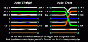
 The easiest thing to distinguish between cable Cross with Straight is the difference between colors in the UTP kabet you can see in the picture above on the cable bahwasannya Cross have different colors with Straight


And as for the purpose or function of cable Cross and Straight as follows

1. Straight Cable

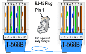
Cables with this combination is used for connections between devices of different types, such as between a computer to the switch, the computer to the hub / bridges, routers to switches, routers to bridge jobs. the color combination we can see in the picture below:


2. Cabel Crossover
Cables with this combination is intended for peer to peer connections between devices similar. Examples from computer to computer, from computer to the router, from switch to switch jobs.
he color combination of the above is based on what lay digunakanan by network technicians and engineers in the world. It facilitates a technician or engineer above the other in tissue repair that have been there before.

For examples of its use:

If there are five computers that will be connected to one switch / hub, the cables used for the device to the computer menghungunkan switch / hub is stright cable Through ...

But if you only want to connect one PC to another PC (PC to a notebook or notebook to notebook) eat you should use a crossover cable

Types of network category

Wireless LAN network or a wireless local network or WLAN is a computer local area network that uses radio waves as a medium tranmisinya, and the last link is used to provide a wireless network connection to all users in the surrounding area.
Area wireless network depends on the strength of the emitted radio waves, the stronger the signal emitted, the range of its network will be more extensive. The backbone network usually uses cables, but the wireless network will need a transmission medium such as cable dipat minimized its use.

IEEE802.11 is a set of specifications medium access control and physical layer for implementing computer communications wireless local area network at a frequency of 2.4, 3.6, 5 and 60 GHz. They created and is operated by the Institute of Electrical and Electronics Engineers (IEEE). The basic version was released in 1997 and has been through a series of updates and provide the basis for wireless networking products Wi-Fi.

Types of IEEE 802.11 Standard
1. IEEE 802.11a
Namely wireless networking standard that works at a frequency of 5GHz with the data transfer speed to 58 Mbps.
 2. IEEE 802.11b
Namely wireless networking standards that are still using the 2.4 GHz frequency at speeds reaching 11 Mbps data trasfer and signal range up to 30 m.
3. IEEE 802.11g
That is a wireless network standard that is a combination of the 802.11b standard uses the 2.4 GHz frequency, but the data transfer speed can reach 54 Mbps.
 4. IEEE 802.11n
Namely the future of wireless networking standard that works at a frequency of 2.4 GHz and is rumored to achieve data transfer speeds of 100-200 Mbps.
The newest IEEE standard in the Wi-Fi category is 802.11n. It was designed to improve the features 802.11g in the amount of bandwidth supported by utilizing multiple wireless signals and antennas (called MIMO technology).
When this standard is complete, 802.11n connections should support data rates of 100 Mbps. 802.11n also offers better range than previous Wi-Fi standards due to increased signal intensity. 802.11n equipment will be compatible with 802.11g devices.
more details can be seen in the following table:
Actually there are several other wireless standards, such as IEEE 802.11j, 802.11h, 802.11p. However, the use of standard was very limited, and umummnya used for application and specific use relating to state regulations and more specific communication applications.


Wireless networks typically work by one of the network topology configuration either Ad-Hoc or Infrastructure network

Function cross cable and straight cable

Function cross cable and straight cablet

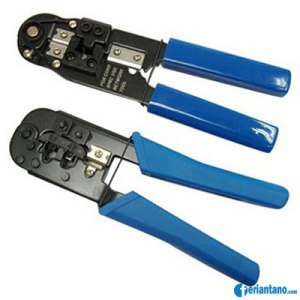
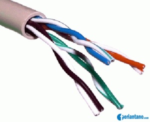
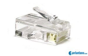
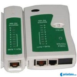
A. the tools needed when making a cross cable and straight cable is as follows:
1. tang crimping
Susunan dan Cara Membuat Kabel UTP Straight dan Cross Lengkap 2
2. kabel UTP
Susunan dan Cara Membuat Kabel UTP Straight dan Cross Lengkap 3
3. Konektor RJ-45
Susunan dan Cara Membuat Kabel UTP Straight dan Cross Lengkap 4
4. Lan Tester
Susunan dan Cara Membuat Kabel UTP Straight dan Cross Lengkap 5
5. Kabel Cross Dan Kabel Straight
cable-utp6
B. Functions
1.Straight Cable Function
Cables with this combination is used for connections between devices of different types. for example, as follows:
  1. Connects the computer to the switch
  2. Connect a computer to the LAN on the cable modem / DSL
  3. LAN router connects with the cable modem / DSL
  4. Connect the switch to the router
  5. Connect the hub to the router
the colors we can see in the image below:
ethcable568b
2. Function Cable Cross
Cables with this combination is intended for peer to peer connections between devices similar. for example, as follows:
  1. Connecting two computers directly
  2. Connect two pieces of switch
  3. Connect two pieces of hub
  4. Connect a switch with a hub
  5. Connect the computer to the router
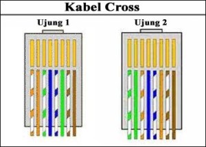
he color combination we can see in the image below:
kabel-cross
C. how to make a straight cable and cross cable
1. Cabel straight
1.Peel the end of the UTP cable, approximately 2 cm. with crimping pliers
2.Open spiral cable, align and sort images according to the standard cable.
3. After the order according to the standard, cut and flatten the ends of the cable. cut using crimping pliers
4. Put the cable is straight and parallel into the RJ-45 connector, and make sure all cables are correct position by position as follows:
Cable ends 1 - end of the cable 2
White Orange - White Orange
Orange - Orange
White Green - White Green
Blue - blue
White Blue - White Blue
Green - green
White Chocolate - White Chocolate
Brown - Brown
5. Perform crimping using crimping pliers, crimping pliers press and make sure all the pins (brass) on the RJ-45 has "bite" each cable. will usually sound "click".
2. Cabel cross
Creating a cross cable has a similar step with a straight cable, the difference lies only in the order of the colors of both ends of the cable. Unlike the straight cable that has the same color sequence on both ends of the cable, the cable cross has a different color sequences at both ends of the cable.

Cable end 1 - 2 cable end
White Orange - White Green
Orange - Green
White Green - White Orange
Blue - blue
White Blue - White Blue
Green - Orange
White Chocolate - White Chocolate
Brown - Brown

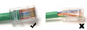
Below is an example of the end of the UTP cable that has an RJ-45 connector is installed properly, the cable sheaths come into the connector.

When one of the sheathing does not go into the connector.

Examples of the picture as follows:
kabel-straight-yang-benar
And the last step we have to do is check the cable that you created earlier by using the tool Lan Tester, how inputs each end of the cable (RJ-45) to each port available on Lan Tester, turn it on and make sure all the lights LED lights up in accordance with the cable sequence that we make. If no lights are not lit LED means that there is an error during a crimping with crimping pliers

Straight sequence UTP cable and Crossover

Share article is about UTP (Unshielded Twisted Pair), this article was a request from my friend adhie YFS, without intending to patronize following is a discussion of the UTP cable that I know.


UTP cable transmission medium is one of the most widely used to create a local network (Local Area Network), but because the price is relatively cheap, easy to install and quite reliable. As the name implies Unshielded Twisted Pair means twisted pair cable / twisted (twisted pair) without protective (unshielded). This convolution function is as elimination of the induction and leakage. Previously there was also cable STP (Shielded Twisted Pair), for example the picture can be seen below:

perbedaan kabel UTP dan STP
   
There are several different categories of UTP cables that show the quality, quantity pairnya winding density, the higher the closer katagorinya windings and other parameters such as the following:
  • UTP cable Category 1 Used for telephone communication (transmits low-speed data), so as not cocock to transmit data.
  • UTP cable Category 2 Capable of transmitting data at speeds up to 4 Mbps (Megabits per second)
  • UTP cable Category 3 Used in 10BaseT network, capable of transmitting data at speeds up to 1Mbps. 10BaseT stands 10 Mbps, Baseband, Twisted pair.
  • UTP cable Category 4 Often used in token ring topology, capable of transmitting data at speeds up to 16 Mbps
  • UTP cable Category 5 capable of transmitting data at speeds up to 100 Mbps,
  • UTP cable Category 5e capable of transmitting data at speeds up to 1000 Mbps (1Gbps), frequency signal that can be passed up to 100 MHz.
  • UTP cable Category  6 Capable of transmitting data at speeds up to 1000 Mbps (1Gbps), frequency signal that can be passed up to 200 MHz. Physically there is a separator which is made of plastic that serves to separate the four pairs in the cable.
  • UTP cable Category 7  
  • gigabit Ethernet (1Gbps), the signal frequency 400MHz
For UTP cabling, there are two types of UTP cabling commonly used in computer networks, especially LANs, namely Straight Through Cable and Cross Over Cable


straight cable

Straight cable is a cable that has the same way of mounting between the end of one with the other end. Straight cables are used to connect two different devices.


Default order straight cable is as below are in accordance with the standard TIA / EIA 368B (the most widely used) or sometimes also used according to the standard TIA / EIA 368A as follows:

kabel jaringan model straight

Examples of the use of a straight cable is as follows:
  1. Connects the computer to the switch
  2. Connect a computer to the LAN on the cable modem / DSL
  3. LAN router connects with the cable modem / DSL
  4. Connect the switch to the router
  5. Connect the hub to the router
Cable cross over
A crossover cable is a cable that has a different arrangement between the end of one
ends of the two. Cross over cable is used to connect two devices together. The picture below is a standard arrangement of wires cross over.

kabel jaringan model cross over

Examples of the use of a crossover cable is as follows:
  1. Connecting two computers directly
  2. Connect two pieces of switch
  3. Connect two pieces of hub
  4. Connect a switch with a hub
  5. Connect the computer to the router
8 pieces of existing wires in the UTP cable (either on a straight or cross-over cable) only four pieces are used to send and receive data, ie no cables on pins 1,2,3 and 6.


Creating Straight and Cross Over Cable

To create a wired network using UTP cable, there are some tools that we need to prepare, the UTP cable, RJ-45 Connector, crimping tools and RJ-45 LAN Tester, sample picture as below:

RJ45 Tang Crimping RJ45 LAN Tester

Practice makes cable Straight
1.Peel the end of the UTP cable, approximately 2 cm
2.Open spiral cable, align and urutankan wiring standards TIA / EIA 368B
3.After the order according to the standard, cut and flatten the ends of the cable,
4.
Put the cable is straight and parallel into the RJ-45 connector, and make sure all the wiring position is correct.

.5Perform crimping using a crimping tool, press the crimping tool and make sure all the pins (brass) on the RJ-45 has "bite" each cable.
6.Once completed at the end of that one, do it again on the other end
7.The last step is pulled-check the cable that you created earlier by using the LAN tester, how inputs each end of the cable (RJ-45) to masing2 an available port on the LAN tester, turn it on and make sure all the LED lights up in accordance with the order of cable we make.
8.Below is an example of the end of the UTP cable that has an RJ-45 connector is installed properly, the cable sheath (blue) come into the connector, cable order from left to right (in the figure below pin cable sequence starting from top to bottom).

pemasangan kabel UTP ke konektor RJ-45

So a quick explanation UTP cable, UTP cable category, standard sequence of straight cable and cross over and how to make a straight network cable using a crimping tools, may be helpful.

Differences in Network Cable UTP Straight and Crossover

Differences in Network Cable UTP Straight and Crossover


UTP cable transmission medium is one of the most widely used to create a local network (Local Area Network), but because the price is relatively cheap, easy to install and quite reliable. As the name implies Unshielded Twisted Pair means twisted pair cable / twisted (twisted pair) without protective (unshielded). This convolution function is as elimination of the induction and leakage. Previously there was also cable STP (Shielded Twisted Pair), for example the picture can be seen below:There are several different categories of UTP cable that shows quality, the number density of winding pairnya, the higher the katagorinya closer the windings and other parameters such as the following: UTP cable Category 1 Used for telephone communication (transmits low-speed data), so as not cocock to transmit data , UTP cable Category 2 Capable of transmitting data at speeds up to 4 Mbps (Megabits per second) cable UTP Category 3 is used in 10BaseT network, capable of transmitting data at speeds up to 1Mbps. 10BaseT stands 10 Mbps, Baseband, Twisted pair. Cable UTP Category 4 Often used in token ring topology, capable of transmitting data at speeds up to 16 Mbps UTP Category 5 capable of transmitting data at speeds up to 100 Mbps, cable UTP Category 5e capable of transmitting data at speeds up to 1000 Mbps (1Gbps), frequency signal which can be passed to 100 MHz. Category 6 UTP cable Capable of transmitting data at speeds up to 1000 Mbps (1Gbps), frequency signal that can be passed up to 200 MHz. Physically there is a separator which is made of plastic that serves to separate the four pairs in the cable. Category 7 UTP cable gigabit Ethernet (1Gbps), signal frequency of 400 MHzIn the lan network using Ethernet or commonly known two types of network cables that STRAIGHT and CROSS, both of which have different functions in the network connectivity. STRAIGHT cable generally used for mengghubungakan connections from Port on Switch / Hub, and CROSS cable is used for point to point connection between two computers connected via ethernet card.To distinguish and STRAIGHT CROSS cable is to look at the color arrangement of pins on the connectors RG 45 which consists of 8 different colors. I'll explain how to prepare the most common colors used for cable termination Straight and Cross (Standard International). 8 colors normally used are Orange (O), White Orange (PO), Blue (B), White Blue (PB), Green (H), White Green (PH), Brown (C), White Chocolate (PC). for some kind of specific quality cables typically only use a single color for all the pins, you must be extra careful to conduct this type of cable termination.1. Cable STRAIGHTTo perform a straight cable terminations usually several ways to apply the twin side which likens the arrangement between the two ends of the connector without regard to the arrangement of colors used.
we use here is the arrangement of colors according to international standards, why do I say international standards, because in the basic curriculum standards are applied cisco academy is sure to be used and as a basic knowlegde for a network technician or engineer one spot is absolutely understandable.

As for the function of each pin can be seen in the picture below

Examples of the use of a straight cable is as follows: Connect the computer to connect the computer to a LAN switch on the cable modem / DSL router with a LAN Connecting the cable modem / DSL router Connecting switches to connect the hub to the router2. Cable CROSSIf the termination of the CROSS cable you are not using prescribed standards or because the cable that you use only has one color for each pinya, you must remember is the sequence.cros cable is a cable that has a different color sequences at both ends of the connector, any arrangement that distinguishes her? from the arrangement of the colors that you have you just swap the stacking order of pin / color at one end of the connector that you plug in which the sequence of colors that are exchanged with the sequence 1 to 3 and the sequence of colors to 2 with the 6th. (1.3) (2.6), then its results as follows:
As for the function of each pin can be seen in the picture below


Examples of the use of cross-over cable is as follows:
  1. Connecting two computers directly
  2. Connect two pieces of switch
  3. Connect two pieces of hub
  4. Connect a switch with a hub
  5. Connect the computer to the router
8 pieces of existing wires in the UTP cable (either on a straight or cross-over cable) only four pieces are used to send and receive data, ie no cables on pins 1,2,3 and 6.


Creating Straight and Cross Over Cable

To create a wired network using UTP cable, there are some tools that we need to prepare, the UTP cable, RJ-45 Connector, crimping tools and RJ-45 LAN Tester, sample picture as below:

Practice makes cable Straight:
  1. Peel the end of the UTP cable, approximately 2 cm
  2. Open spiral cable, align the cable and sort according to the standard TIA / EIA 368B
  3. After the order according to the standard, cut and flatten the ends of the cable,
  4. Put the cable is straight and parallel into the RJ-45 connector, and make sure all the wiring position is correct.
  5. Perform crimping using a crimping tool, press the crimping tool and make sure all the pins (brass) on the RJ-45 has "bite" each cable.
  6. Once completed at the end of that one, do it again on the other end
  7. The final step is to check the cable that you created earlier by using the LAN tester, how inputs each end of the cable (RJ-45) to masing2 an available port on the LAN tester, turn it on and make sure all the LED lights up in accordance with the order of cable that we created.
  8. Below is an example of the end of the UTP cable that has an RJ-45 connector is installed properly, the cable sheath (blue) come into the connector, cable order from left to right (in the figure below pin cable sequence starting from top to bottom).